Good explanation about Differentiation
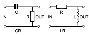
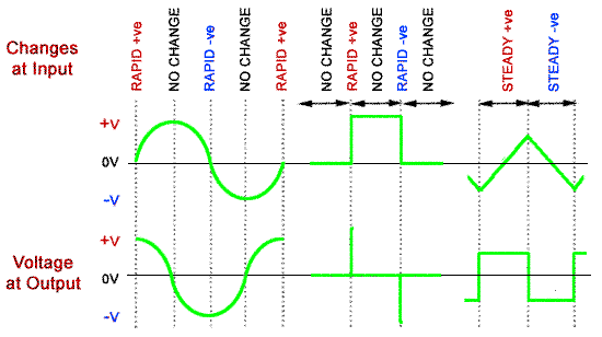
“The output wave of a DIFFERENTIATOR CIRCUIT is ideally a graph of the rate of change of the voltage at its input.”

Fig.8.4.1 The Differentiator Circuit

Fig 8.4.2 Differentiation.
——————————————————————————————–
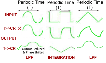
“The shape of the input wave of an integrator circuit in this case will be a graph of the rate of change of the output wave ”
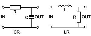
“The low pass filter circuit is therefore called an integrator only when:
a. The input wave is a square wave.
b. The periodic time(T) of the input wave is much shorter than the circuit time constant(CR) i.e.(T<=CR).”

Fig. 8.5.1 The Integrator (also low-pass filter) Circuit.

Leave a Reply