
I consider myself not bad in fixing electronics considering it is just my hobby. But for a long time I was hesitant to touch switched mode power supplies unless I see something obvious – leaked capacitors, blown up IC`s or diodes etc. There are couple of reasons for it: high voltages, lack of schematics, no isolating transformer. Recently I got myself Robotronics 1715 personal computer and after first inspection it was obvious that its power supply is bad. 12V rail to be exactly. And it is switching mode power supply. I really wanted to make this thing alive again and so my long journey began. Journey during which I had probably made more mistakes than good moves and blown up couple of components in this power supply by myself. I will not go through the all details as as I was fixing it for couple of weeks but I was just too stubborn to stop. What I will do here is put some lessons learned and notes about fixing this and some other switching mode power supplies.
So, lessons learned:
Always use load. Sometimes smps will trick you that it is not working and what is happening it is just not having load and that’s why it is not turning on. Learned it the hard way.
Get as much details about it as possible first. By debuging this supply I was tricked by some clever circuitrly that I was confused what it was doing and later when I found that this supply has to enable 12v rail with a delay and disable it first before disabling 5v rail – everything stood on their places and it was like a lightbulb in my head.
Use isolating transformer. Really – USE IT! I was always hesitant to get one, but when I was stuck with this supply, I really had to test it with a scope and you know the rest. I was trying to be careful, later I was using two probes and a math diff, but anyway, you make a mistake and see magic smoke sooner or later. I knew that it might happen and it happened. So later I just went to shop, bought a 220v to 220v transformer, wired it up and now life is much much easier.
What I have replaced:
F1, F2 fuses. Were blown.
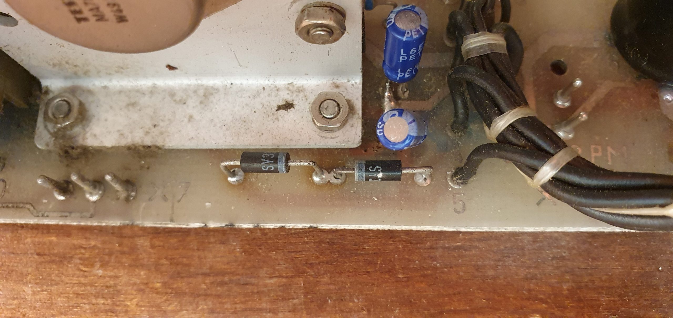
V1,V2,V3,V4 diodes, 3 of 4 were bad. Replaced with some other genera purpose diodes.
C117, C120, C13, C14, C15, C125, C126, C107, C225, C7, C8, C9 electrolytic capacitors.
N105 – it was not working.
V21, V20 – diodes.
V15 transistor. It was bad.
V125 transistor. Originally it was SC236D. Replaced it with general 2N2222A. But for it to work, I had to add 56K resistor to the base of V19.
It took most time to find failed V125, find replacement for it and make it work correctly. 2N2222A did not work initially as, as I understand, it was providing too much current to V19 and V19 was too open. Adding resistor to base of V19 fixed everything.
V125 is final part of delay circuit.
For the correct operation of Robotron 1715, voltages must be provided in certain sequance. 12p must be provided after 5p, but switch off before the 5p. The 12p is made switchable via transistors v18, v19. When a base current is fed into transistor v19 via R137, it switches on and supplies the control current for V18. The fuse F3 is provided to protect the transistor from overload. In the event of a power failure or a network breakdown, the 12p must be switched off before the 5p. This switching behavior is implemented by monitoring the DC line voltage UEP via the voltage divider R121, R120. This monitoring is carried out by the operation amplifier N104. UEP is compared with the reference voltage of the N105 between connections 2 and 3. The switching threshold is set with R120 at UEP 195v.
If UEP is above 195v, the operational amplifier is conducting and the coupler U103 carries current, which results in HIGH at R135. The trigger N103 generates a delay of approx. 3 s between 5p and 12p with the help of R133, C113.
After the delay time has elapsed, the output of the trigger becomes HIGH and V125 is turned on via R134, V116, V117.
Thereby the switching amplifier controls the 12p. If the network fails, the power supply from the capacitor C3 is buffered until the switching threshold of the UEP of 195v is reached. Now the 12p switches off. The 12p remains at its full level until the control area is reached. The 5p control track still works up to a voltage UEP of about 160v.

Hi, Thank you for sharing this. What is the circuit with V19 used for? it shorts the 5V line with the 12V line limiting the current. Indeed if the V19 is saturated / fully open it may allow for too high current pass between 5 and 12V lines and destabilise the power supply, so why have the V19 connected at all? It looks the system might work fine without V19 as well.