
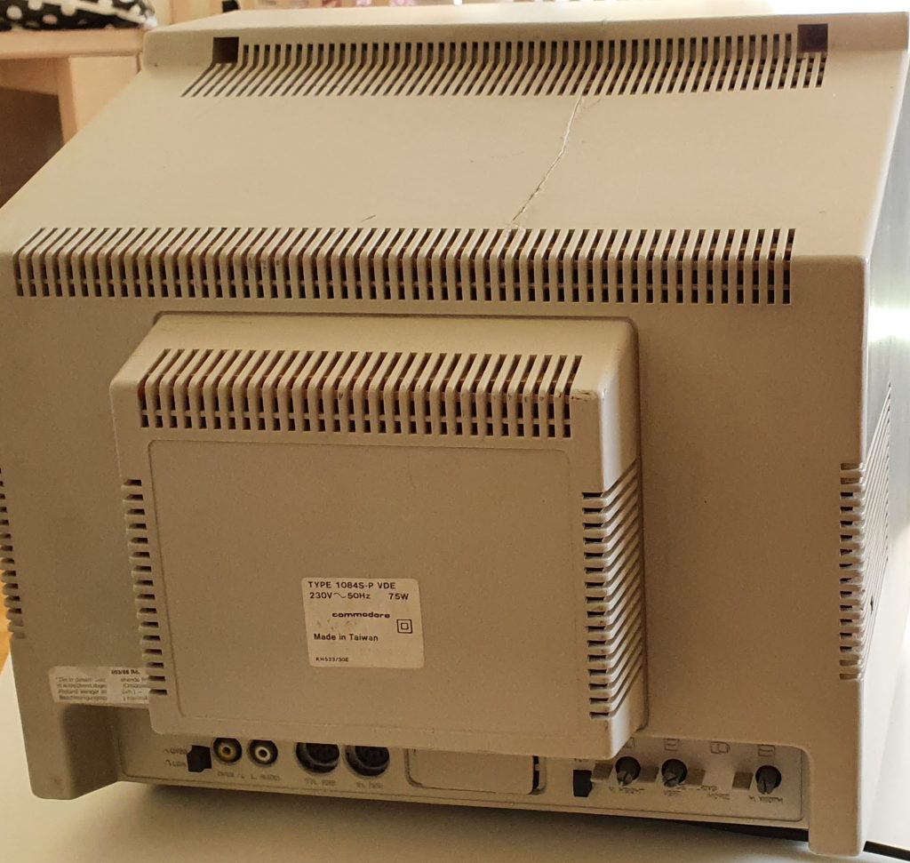
One day I was craving for a monitor. Not a regular Liquid Crystal Display or Light Emitting Diode type, but for an old Cathode Ray Tube monitor. The one that clicks and buzzes when you turn it on. The one that could heat a small apartment room. The one that takes all the useful space on your desk. The one that makes Your electricity bill considerably larger. The one that has high voltage inside it. And the one that usually is in a dumpster nowadays. Why would one need such an antique? Well, I own a couple of antique computers from the ’80s and decided that I would like to have a small versatile crt monitor which I could use with all of them or most of them. Usually, “modern” monitors have standard VGA input, but I needed something with RGB and composite inputs, analog inputs. I remembered that I saw some small Commodore monitors that were something I was looking for. There is a nice site that lists all Commodore monitor models and all their information and manuals. Good information. For geeks and collectors. Ok, so after a quick search on ebay somewhere around me, I found one Commodore 1084S-P VDE for sale. Not working. Not a big deal I thought. I know how to hold a solder iron and read schematics and with a power of some googling I will definitely be able to fix it. Considering crt itself is alive. So I bought it.
While waiting for it to arrive I have gathered as much information as possible about this device. It has analog RGB, digital RGBi, PAL separate, and PAL composite inputs (NTSC). Mine had din connectors for RGB, so probably it is NTSC after all. MAximum resolution 640 lines in center ( if it is NTSC). Manufactured in 1988 in Taiwan.
How do they fail? Well, it seems usual failure for those monitors are flyback transformer (FBT) (or also called line output transformer LOPT) and horizontal line output transistor (called HOT). Flyback generates high voltage for the tube to drive its ray and the horizontal line output transistor drives the flyback transformer itself by switching it on and off. Of course and other usual things like old electrolytic capacitors.
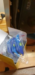
So I have ordered replacement LOPT for it. According to the description, HR7506 is a proper replacement. I bought one from retronics.eu ebay store. By the way, thanks for the candies, that was a nice touch! 🙂
Also, I bought a couple of transistors to replace HOT. I have found somewhere that BU508A is a good replacement.
When the monitor has it arrived I saw that its cover has some nasty cracks and is broken in some places. Ok, let’s see what is inside. The initial test after the lid was removed.
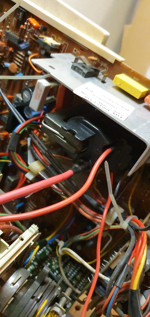
You could hear this poor guy whinnying. I have slid the mainboard out just a little bit just to get to the LOPT so I could replace it. That was my first mistake.
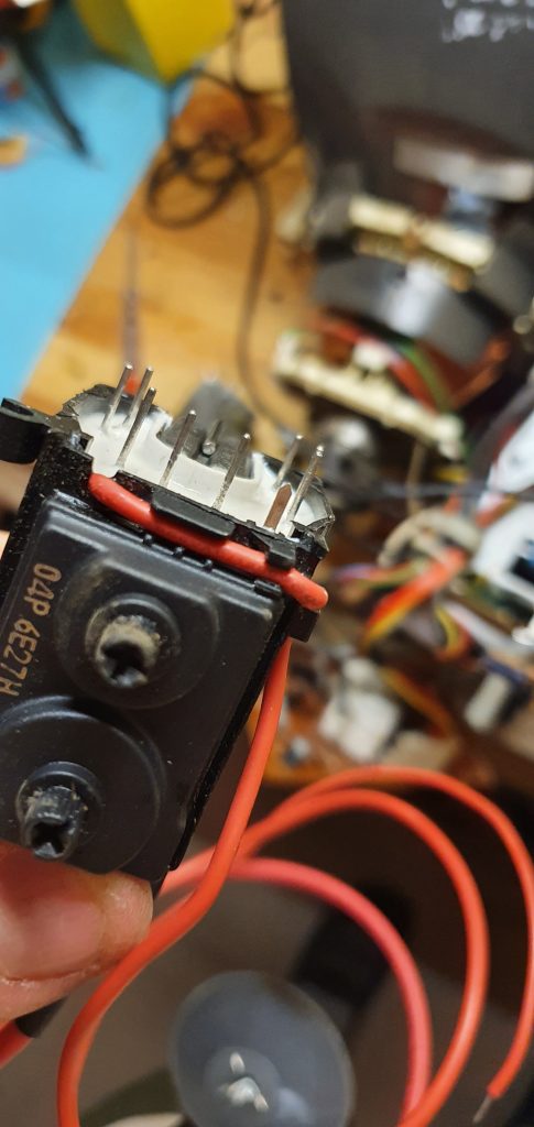
I have removed LOPT and installed new one. By the way. It seems that HR7506 is a proper replacement but its ground pint is different and in different location. What I did is I have attached some wire to LOPT ground pin and solderent other end of it to old pins location on the pcb.
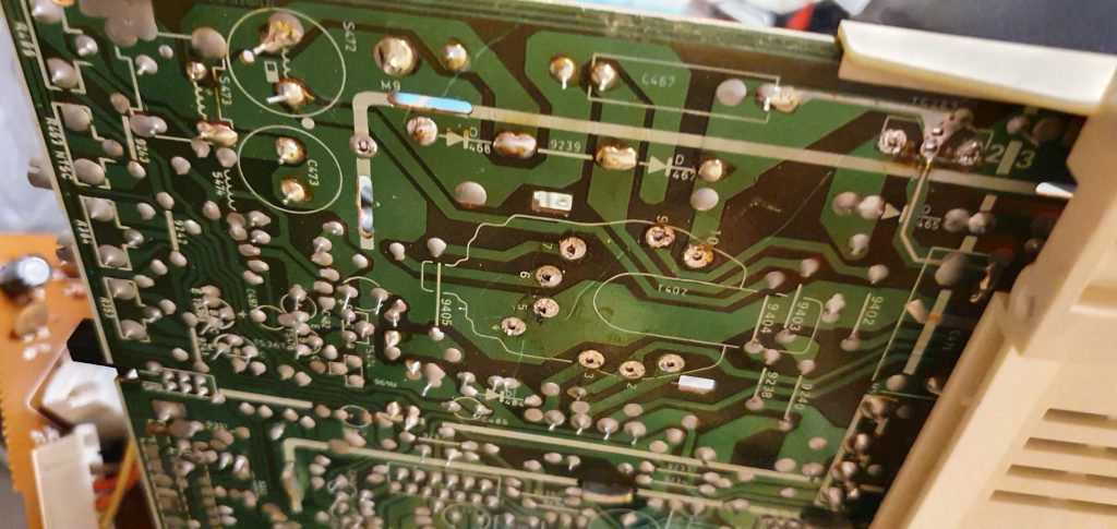
When I have turned on the monitor to test it after the new LOPT installation I heard just some small crack and silence. Nothing. Brightness controls did nothing. The tube was not glowing. It was dead. Even it whinnied before. That was depressing. So I removed everything again and also decided to fully remove the main PCB board. And then I found this.

It seems PCB was broken in several places. Traces were cracked off course. Ok, no big deal. The components on the PCB itself seemed ok, not broken. It is a single-sided PCB, without any internal layers, so maybe I can fix it. With some swearing, multimeter, soldering iron, and small wires I have traced all the places that needed to be fixed and had no continuity. Then soldered some jumper wires and covered everything with Kapton tape.
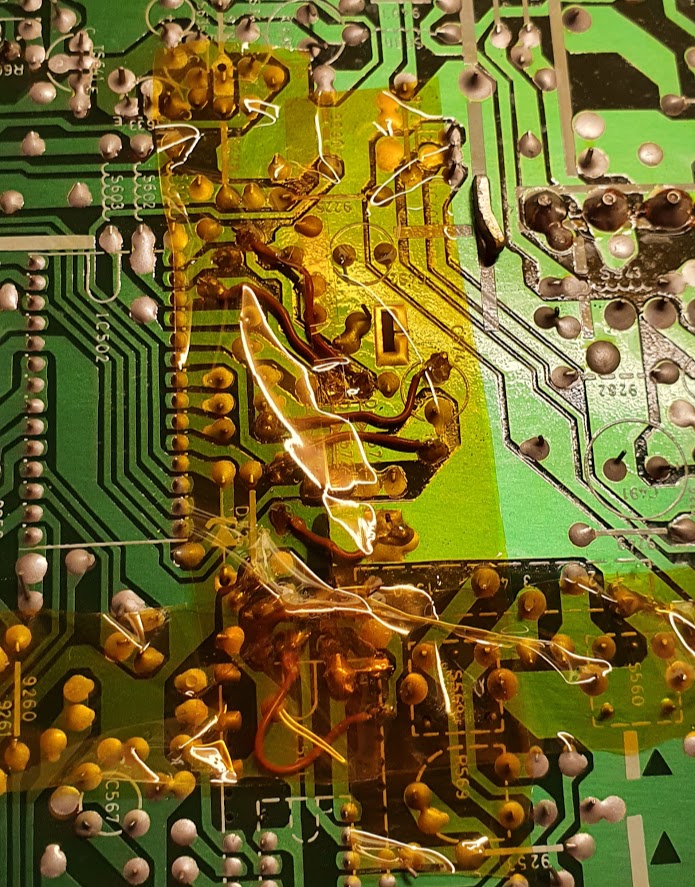
There were also couple of places on the edges of pcb where I did same fix.
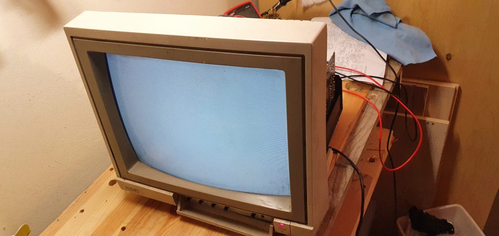
After that, it was time for the test again. When I turned it on I heard some static electricity sound, saw that cathode of CRT was glowing and that is it, no light on the CRT itself. It seems high voltage was generated after all as when I have discharged CRT I heard a loud crack, that was not the case before. So I decided to replace HOT transistor as I still was using the old one. I don’t know why I decided to do that, but that was my second mistake.
After the new HOT installed was installed, when turned on the monitor was whining again, even louder, CRT cathode not glowing. After turning it off and discharging there was no crack, so probably no high voltage.
I have tried to test old and new transistors with Chinese transistor tester, but all I was getting for all of them is that it is a diode. I have tested some resistances and compared old transistor with a new one and got a feeling that the old transistor is not at all dead.
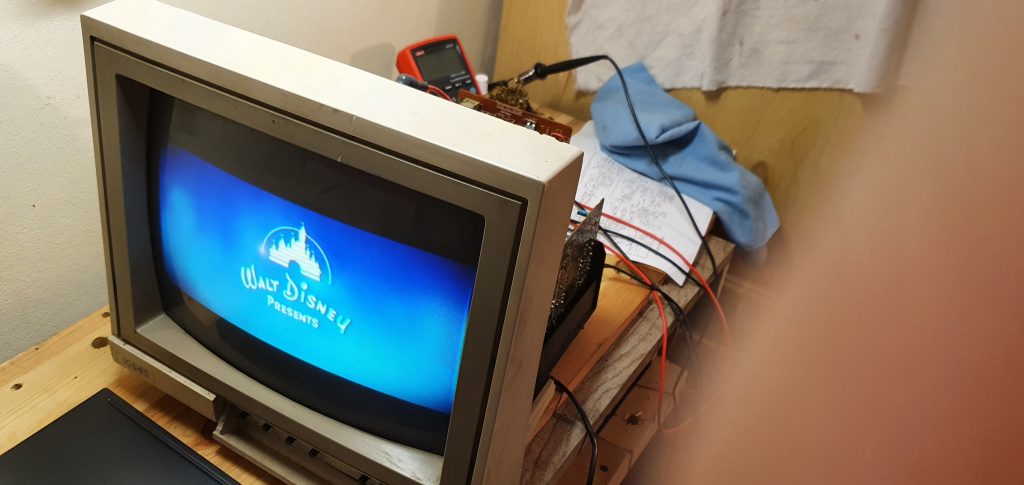
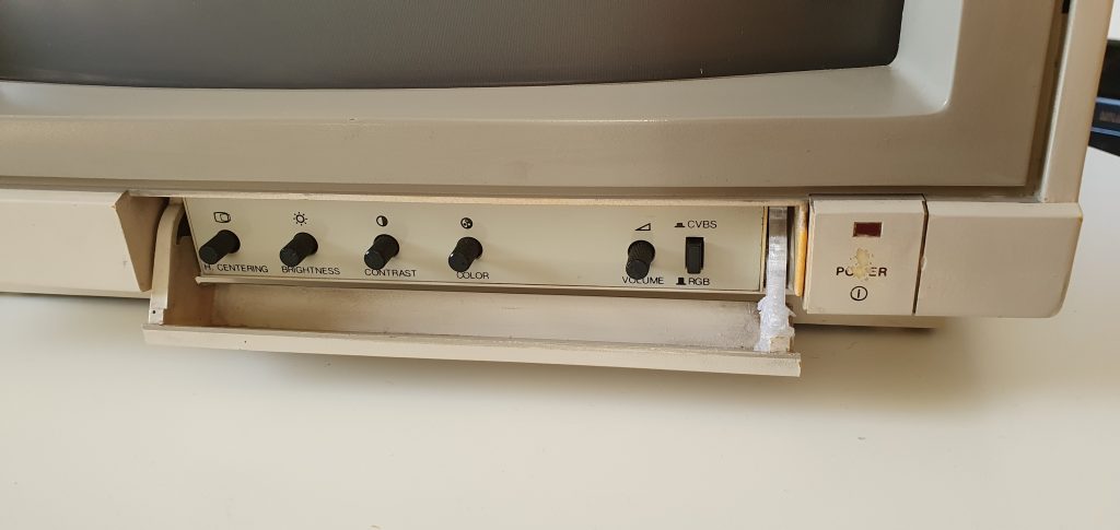
So as it was showing more signs of life with the old transistor I decided to test with once more. Again, CRT cathode was glowing but dar screen. And then I have remembered that LOPT has two adjusting screws – brightness and contrast and when I have turned brightness a bit – IT WAS ALIVE!
Then I quickly connected some old DVD player just to test if it would show anything, and it was working!
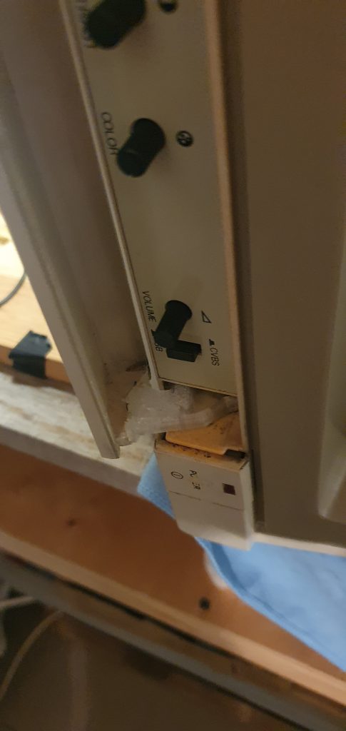
And that is it. I have reassembled everything and did some cleaning. One end of the lid was broken, so I have just made a rough copy with Fusion 360, 3d printed and it glued it. That worked out nicely.

And it did not exploded and I was not zapped with high voltage, that`s nice 🙂
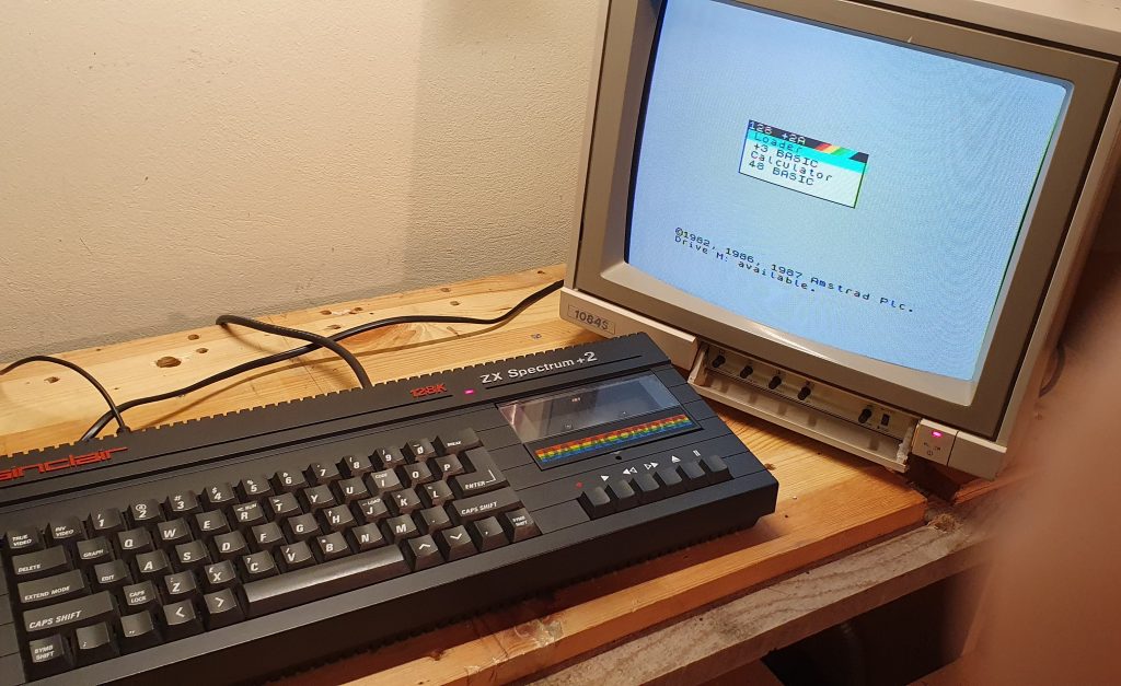
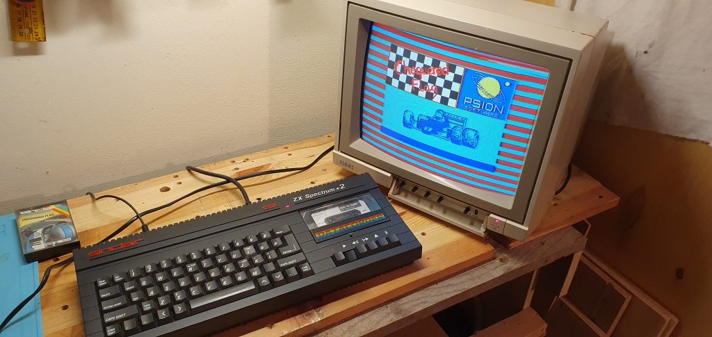
Then I tried to connect this monitor to ZX Spectrum +2. Previously I have made ZX Spectrum +2A composite mod, so connecting was straightforward. Results below.
Leave a Reply